
Guangzhou, Guangdong, China – October 21, 2026 – Choosing an Air Solenoid Valve in 2026 requires more than comparing port sizes and catalogue prices. Compressed-air systems are becoming smarter, but their basic failures remain familiar: pressure drops, contaminated air, slow cycling, and overheated coils. In a factory, these problems appear as a cylinder stopping halfway, a hissing fitting, or an actuator moving several seconds late.The market is expanding steadily. Grand View Research identifies industrial automation as a major driver of solenoid valve demand, while MarketsandMarkets links growth to process control, pneumatic equipment, and connected manufacturing. Their forecasts differ in market scope and growth rate. That matters. Report numbers should guide decisions, not replace engineering judgment. ISO 4414 remains a useful reference for pneumatic safety and system design, especially when valve exhaust, pressure isolation, and unexpected movement are considered. IEC 60204-1 also deserves attention when electrical control panels and machine safety are involved.A practical selection process begins with the application. Confirm working pressure, temperature, flow requirement, media quality, response time, voltage, duty cycle, and installation environment. Then inspect the real air line, not only the specification sheet. Moisture at the filter bowl can change the choice completely. A direct-acting Solenoid Air Valve may suit small flows and simple control, while a pilot-operated design can deliver higher flow with cleaner, stable air. Neither option is universally better. We should admit one weakness in many buying guides: they simplify maintenance. Coil replacement, seal compatibility, spare-part access, and testing intervals often decide lifetime cost. This guide examines those trade-offs for engineers, maintenance teams, and responsible buyers planning reliable pneumatic equipment in 2026.

What Is an Air Solenoid Valve and How Does It Work?
An Air Solenoid Valve controls compressed air through an electrically operated coil. When the coil receives voltage, it creates a magnetic field. The field moves a plunger, opening or closing an internal passage. Without power, a spring usually returns the valve to its normal position. This simple action can move a cylinder, clamp a component, or release pressure within milliseconds.
Selection begins with the application, not the catalog photograph. Check port size, operating pressure, flow rate, voltage, response time, and duty cycle. A normally closed valve suits many safety-oriented pneumatic controls. A normally open design may be better when airflow must continue during power loss. The U.S. Department of Energy reports that compressed-air leaks can waste 20–30% of compressor output. Therefore, sealing quality matters as much as electrical efficiency. ISO 4414 also emphasizes safe pneumatic design, isolation, and controlled exhaust.
Tips: Confirm the required flow using the valve’s Cv or equivalent rating. Measure pressure at the machine, not only at the compressor. Select coil voltage carefully, and verify connector protection against dust or moisture. My first selection mistake was choosing a larger valve for “extra capacity.” It responded slowly and consumed more air. That assumption was flawed. In 2026, valves with position feedback and diagnostic monitoring can support predictive maintenance, but sensors add wiring, cost, and failure points. Use them where downtime justifies the complexity. Test the Air Solenoid Valve under real temperature, pressure, and cycling conditions before approving full production.
Identify the Application and Required Valve FunctionHow to Choose an Air Solenoid Valve in 2026?
Start with the task. Identify what the valve must control before comparing specifications. A pneumatic cylinder may need simple extension and retraction. An air blow-off nozzle may require fast, repeated bursts. A vacuum circuit needs different porting and sealing considerations. Write down the operating pressure, air quality, flow demand, cycle frequency, and available voltage.
Then define the required valve function.A normally closed valve blocks air when power is removed. This can help prevent unexpected movement during a shutdown. A normally open valve may suit systems that must continue venting without electrical power. For cylinder control, check whether a 3/2, 5/2, or 5/3 configuration matches the actuator. Select the port size from actual flow requirements, not pipe diameter alone. A larger body does not always produce better performance.
I have seen valves selected by catalog pressure ratings alone. That approach can fail. The machine may operate correctly on a bench, then respond slowly after filters become dirty. Consider response time, exhaust capacity, temperature, moisture, and continuous-duty coil heating.
Confirm that the Pneumatic Air Solenoid can handle the media and installation environment. I also recommend testing the valve during the worst expected cycle, with real tubing and fittings. Small pressure drops become obvious there. Check the fail position carefully, because a convenient choice is not always the safest one.
Select the Correct Valve Type and Port ConfigurationHow to Choose an Air Solenoid Valve in 2026?
Selecting the correct valve type starts with the actuator’s movement. A single-acting cylinder usually needs a 3/2 valve, with normally closed or normally open operation. A double-acting cylinder generally requires a 5/2 valve. Use a 5/3 valve when the cylinder needs a defined center position. That choice affects safety, response time, and compressed-air use.The U.S. Department of Energy reports that leaks can waste 20–30% of compressor output.The wrong exhaust path can increase that waste.
Port configuration deserves equal attention. Match the valve’s inlet, outlet, and exhaust ports with the actuator layout and tubing size. Check thread standards carefully, because a fitting may look compatible and still leak. ISO 5599-1 and ISO 15218 provide useful references for pneumatic valve interfaces and mounting dimensions.For compact machinery, a manifold can reduce tubing length and simplify maintenance. However, it can also make troubleshooting less obvious.I have seen technicians replace a valve when the real problem was a restricted silencer.
Review pressure range, flow rate, response time, coil voltage, and operating temperature together. Do not select a valve only by port size. A larger port may add cost without improving cylinder speed. The DOE also notes that pressure losses force compressors to work harder. Measure actual demand at the machine, not only the compressor outlet. Leave a practical margin, but avoid excessive oversizing. Small details matter. Industry reports help, but field measurements remain decisive.
Match Pressure, Flow Rate, Voltage, and Response RequirementsHow to Choose an Air Solenoid Valve in 2026?Match Pressure, Flow Rate, Voltage, and Response Requirements
Choosing a Valve Solenoid in 2026 starts with the machine’s actual conditions, not a catalog headline. Measure inlet and outlet pressure while equipment runs, because static readings can mislead. Select a pressure rating above the highest observed value, including start-up surges. Then estimate the required flow at the working pressure and temperature. A valve that opens quickly may still starve a cylinder if its orifice is too small. I have seen this mistake cause slow actuators and unnecessary troubleshooting. Use flow coefficient data, and verify whether it applies to air, vacuum, or another approved medium. Keep the target clear.
Voltage and response time deserve equal attention. Match the coil voltage to the control system, such as 24 V DC. Confirm tolerance, power draw, and connector wiring. Never assume a “24-volt” output is clean or stable. Electrical noise and voltage drop can create intermittent operation. For fast indexing, compare opening and closing times under real pressure, not ideal bench conditions. Consider duty cycle and heat around the coil. Continuous energizing can change performance. Select normally open or normally closed operation according to the safe state needed during power loss.
Tips:Record pressure, flow, voltage, temperature, and cycle frequency in a simple test sheet. Check seals against air quality and lubricant use. Leave service space around the valve. If response is inconsistent, inspect wiring before replacing hardware. That habit saves time. My selection sheets have changed after field failures; reasonable assumptions can fail during a dusty shift. Pilot-operated designs may need minimum pressure, while direct-acting types can respond better at low pressure. Confirm this before ordering.Choose Suitable Materials, Seals, and Environmental Protection
Selecting an air Solenoid Valve starts with the working medium, temperature, pressure, and cycling frequency. Brass suits clean, dry air and moderate industrial conditions. Stainless steel is safer near moisture, cleaning chemicals, or salty air. Aluminum reduces weight, but it needs careful corrosion assessment.Seal selection deserves equal attention. Nitrile seals handle common compressed-air applications and moderate temperatures. Fluorocarbon seals resist many oils and higher temperatures, but they cost more. Polyurethane can perform well under repeated movement, although some additives may shorten its life. The U.S. Department of Energy reports that compressed-air systems can consume 10% or more of a facility’s electricity. Small leakage, poor sealing, and unnecessary pressure can therefore become expensive. I have seen a valve operate correctly during testing, then fail early after water entered the line. Laboratory results are not the whole installation.Tips: Check the ISO 8573-1 air-quality class before choosing seals. Confirm the temperature range, not only the average temperature. For outdoor equipment, select an enclosure rating under IEC 60529, such as IP65 or higher when dust and water jets are expected. Mount the valve away from direct spray, and add drainage where condensation collects. Leave a service margin of 10–20% for pressure and temperature when practical. That margin is not universal. Process conditions still need verification.
How to Choose an Air Solenoid Valve in 2026?
Typical continuous operating temperature ranges for common seal materials
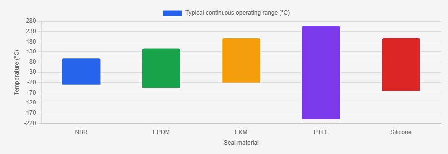
Seal selection should match the air temperature, moisture, chemicals, and duty cycle. NBR is a cost-effective choice for general compressed air, EPDM performs well with hot water and steam, FKM suits oils and many chemicals, PTFE provides the widest temperature resistance, and silicone remains flexible at low temperatures. For outdoor or washdown installations, also select corrosion-resistant valve materials and an enclosure rated at least IP65.
Check Installation, Maintenance, Safety, and Future Replacement Needs
How to Choose an Air Solenoid Valve in 2026?Choosing an air solenoid valve starts with the installation environment. Check pipe size, pressure range, air quality, temperature, and available space. A compact valve may fit neatly, but crowded tubing can make future servicing difficult. Leave room for coil removal and manual testing. I have seen small installation shortcuts create large maintenance delays. The mistake was avoidable.Maintenance needs should shape the selection. Choose a valve with accessible seals, clear flow markings, and replaceable service parts. Add a filter and drain moisture before it reaches the valve. Inspect connections for leaks during scheduled shutdowns. Listen for delayed switching or unusual clicking. These signs often appear before failure. Still, inspection schedules are not perfect. Dust levels and operating cycles can change unexpectedly.Tips: Record the valve’s model, voltage, port size, and installation date. Keep one compatible replacement available when downtime is costly. Confirm electrical protection before connecting the coil. Use approved wiring practices and isolate pressure before service. Review emergency shutoff access with the maintenance team. A future replacement may have different dimensions, even when specifications look similar. Photograph the original piping before removal. Small details matter.
How to Choose an Air Solenoid Valve in 2026? – Check Installation, Maintenance, Safety, and Future Replacement Needs
| Selection Area | What to Check | Practical Selection Data | Installation and Maintenance Guidance | Safety and Future Replacement Considerations |
|---|---|---|---|---|
| Working Medium | Confirm that the valve is intended for compressed air and identify possible contamination from oil, water, dust, or process chemicals. | Use a valve specifically rated for compressed air. For general pneumatic systems, air quality is commonly managed with filtration at approximately 5 micrometres or finer when required by the equipment. | Install a suitable filter and drain accumulated condensate. Keep pipe interiors clean and prevent sealing tape or debris from entering the valve. | Do not use an air-only valve for oxygen, flammable gases, steam, or aggressive chemicals unless the manufacturer explicitly approves the application. |
| Operating Pressure | Check the minimum and maximum inlet pressure, pressure fluctuations, and whether the valve must operate at zero differential pressure. | Many industrial pneumatic valves operate within a range around 0.1 to 0.8 MPa, but the exact range depends on the valve design. Direct-acting valves are generally better suited to low or zero differential pressure. | Install a pressure regulator where the supply can exceed the valve rating. Verify pressure during start-up and under the actual flow load. | Never exceed the body, seal, or coil ratings. A pilot-operated valve may fail to shift if the available differential pressure is below its stated minimum. |
| Flow Capacity | Match the valve flow capacity to cylinder size, actuator speed, tubing length, and the required cycle time. | Compare the manufacturer’s Cv, Kv, or standardized flow data. A larger nominal port does not automatically provide higher usable flow if the internal passage is restrictive. | Use an exhaust muffler that does not excessively restrict flow. Keep tubing runs as short as practical and avoid unnecessary elbows. | Insufficient flow can cause slow or incomplete actuator movement; excessive flow can create impact, noise, and unstable motion. |
| Valve Function | Determine the required number of ports and switching positions, such as 2/2, 3/2, 5/2, or 5/3. | Use 2/2 for simple on/off air isolation, 3/2 for single-acting actuators, 5/2 for most double-acting cylinders, and 5/3 when a defined center position is required. | Confirm port labels and flow direction before connecting tubing. Test every switching position at low pressure before normal operation. | Choose the correct fail position: normally closed, normally open, exhaust-center, pressure-center, or closed-center according to the machine risk assessment. |
| Actuation Method | Compare direct-acting, pilot-operated, and internally or externally piloted designs. | Direct-acting designs suit smaller flows and low-pressure operation. Pilot-operated designs normally provide higher flow with lower electrical power but require suitable pilot pressure. | For pilot-operated valves, maintain clean, dry air and verify that the pilot passage is not blocked by particles or seal fragments. | Use a design that remains predictable during low-pressure start-up, pressure loss, and recovery. Check the specified response time if timing is safety-related. |
| Voltage and Electrical Supply | Check coil voltage, AC or DC type, tolerance, power consumption, connector type, and control-system compatibility. | Common control voltages include 24 V DC and 110–120 V AC; 24 V DC is widely used in industrial control panels. The actual coil rating must match the available supply. | Measure voltage at the coil terminals during operation. Protect the circuit with correctly rated fusing and use surge suppression where appropriate. | Do not energize an AC coil with DC or a DC coil with AC. Allow for heat dissipation and observe the permitted duty cycle. |
| Environmental Protection | Assess dust, water, oil mist, vibration, ambient temperature, and outdoor exposure. | Select an enclosure rating suitable for the location, such as an appropriate IP rating. Typical industrial temperature limits are often near 0 to 50 °C, but the valve and coil datasheets control. | Mount the valve away from direct heat, heavy vibration, and water spray. Use protected cable entries and install drainage where condensation is possible. | Outdoor, washdown, hazardous-area, and high-temperature applications may require special construction or certification. |
| Connection and Mounting | Verify port thread standard, port size, mounting orientation, available space, and access for coil removal. | Common thread standards include BSPP, BSPT, and NPT; these are not interchangeable. Select the correct thread and sealing method for the piping system. | Use two wrenches when tightening fittings to avoid twisting the valve body. Follow the specified torque and leave enough clearance for maintenance. | Incorrect thread engagement or excessive sealant can damage the body or obstruct the flow path. Support heavy tubing and manifolds independently. |
| Sealing Materials | Match elastomer and body materials with temperature, lubricant, moisture, and chemical exposure. | Common seal materials include NBR, FKM, and EPDM. Their suitability varies; for example, EPDM is generally unsuitable for many mineral-oil applications, while material compatibility must be confirmed for each medium. | Use only lubricants approved for the selected seal material and air system. Avoid mixing incompatible replacement seals. | Material incompatibility can cause swelling, cracking, leakage, or sudden failure. Record the seal material for future replacement. |
| Installation Testing | Check leakage, switching, flow direction, electrical operation, and actuator movement after installation. | Test at a controlled pressure first, then at normal operating pressure. Confirm that the actuator reaches both required end positions without abnormal noise or delay. | Use a leak-detection solution or an approved electronic method around joints. Never search for leaks with hands near pressurized connections. | Isolate and depressurize the system before correcting leaks, changing tubing, or removing the valve. |
| Routine Maintenance | Monitor leakage, response time, coil temperature, noise, filter condition, and cycle performance. | Set inspection intervals based on cycle frequency and air quality. High-cycle or contaminated systems require more frequent checks than clean, lightly used systems. | Drain filters, inspect fittings, clean external surfaces, check electrical terminals, and replace damaged seals or silencers using approved parts. | Do not disassemble a pressurized valve. Lock out electrical and pneumatic energy before service and verify zero stored pressure. |
| Safety Function | Identify the safe state required when power, air pressure, or a control signal is lost. | Choose normally closed, normally open, or a defined directional center condition according to the risk assessment—not merely according to convenience. | Test the loss-of-power and loss-of-air behavior during commissioning. Document the result in the machine maintenance record. | A solenoid valve alone may not provide a complete safety function. Safety-rated isolation, monitoring, redundancy, or a certified safety circuit may be necessary. |
| Noise and Exhaust | Consider exhaust noise, switching shock, and the working environment. | Use a suitable muffler or exhaust flow-control device where allowed. The device must not reduce exhaust capacity below the actuator’s requirements. | Inspect silencers for clogging and replace them when back pressure or slow movement develops. | Never block an exhaust port to reduce noise. Excessive back pressure can change the actuator’s behavior and create a hazard. |
| Expected Service Life | Review mechanical cycle life, electrical duty, operating frequency, pressure, and environmental conditions. | Cycle-life figures are design-specific and may range from millions to tens of millions of cycles under stated laboratory conditions. Treat the published value as application-dependent. | Track cycle count where practical and replace wear parts before leakage or switching failure affects production. | Do not use a cycle-life number without checking its test conditions, pressure, voltage, temperature, and maintenance assumptions. |
| Future Replacement | Record all dimensions and performance data needed to source an equivalent valve later. | Document function, ports, thread standard, flow rating, pressure range, coil voltage, connector, seal material, temperature range, mounting pattern, and enclosure rating. | Keep a clean photograph, wiring detail, valve label, installation drawing, and spare-seal information in the equipment record. | Prefer standardized interfaces and readily available coil and seal replacements. Confirm interchangeability rather than relying only on nominal port size. |
| Spare Parts and Stock | Estimate downtime impact and identify the parts most likely to fail. | For critical equipment, consider stocking at least one complete replacement valve, spare coil, connector, seal kit, and compatible mufflers according to risk and lead time. | Store components in a clean, dry location and protect seals from heat, sunlight, ozone, and contamination. | Verify that stored spares have the same electrical and pneumatic specifications before installation. |
| Final Selection Check | Confirm every specification against the actual machine conditions, not only the original valve dimensions. | The selected valve should satisfy medium, pressure, flow, function, voltage, temperature, environment, connection, safety, and replacement requirements simultaneously. | Complete a documented commissioning test and establish inspection intervals based on operating data. | When the application affects personnel safety, have the complete pneumatic and electrical safety design reviewed by a qualified professional. |
Important: Pressure, temperature, flow, cycle-life, sealing, and enclosure values are application-dependent. Always verify the final selection against the current technical documentation and the machine risk assessment.
WENK Pneumatic S-AS Push-to-Lock Elbow Speed Control Valve: Features, Benefits, and Applications

WENK Pneumatic S-AS Push-to-Lock Elbow Type Speed Control Valve
In modern pneumatic automation, precise actuator speed control is essential for repeatable motion, reduced vibration, and longer component life. The push-to-lock elbow speed control valve combines tool-free adjustment with a secure locking mechanism, allowing operators to set airflow quickly and prevent accidental changes during operation. Its compact elbow configuration also helps conserve installation space, making it suitable for compact machinery, robotic tooling, packaging equipment, and assembly lines. The growing demand for reliable automation is reflected in the International Federation of Robotics’ World Robotics report, which recorded more than 541,000 industrial robots installed globally in 2023.Constructed with a brass body and electroless nickel plating, the valve offers dependable mechanical strength and corrosion resistance in demanding industrial environments. Its high-strength PBT knob and release sleeve support repeated adjustment, while compatibility with nylon, soft nylon, and polyurethane tubing simplifies integration with existing pneumatic circuits. Operating across 0°C to 60°C and 0.1–1.0 MPa, it provides stable performance for a wide range of actuator-control requirements.For maintenance teams, the push-lock design can reduce setup time by eliminating the need for adjustment tools. Engineers can fine-tune cylinder extension or retraction speed directly at the connection point, supporting smoother indexing, clamping, lifting, and positioning operations. Its space-efficient structure is particularly valuable where conventional inline valves would increase tubing length or interfere with surrounding components.
Conclusion
Choosing the right Air Solenoid Valve in 2026 begins with understanding how it uses an electrical signal to control the flow of compressed air through an internal mechanism. Start by identifying the application, operating conditions, and required function, such as on/off control, directional switching, or flow regulation. Then select the appropriate valve type, number of ports, and configuration to match the system design.Before making a final decision, verify the required pressure range, flow capacity, voltage, response speed, and duty cycle. Materials and seal types should be compatible with the air quality, temperature, moisture, and surrounding environment, while suitable protection ratings can improve reliability in demanding locations. Also consider installation space, connection standards, maintenance access, safety requirements, and the availability of replacement parts. A well-matched valve should provide dependable performance, efficient operation, simple servicing, and flexibility for future system upgrades or replacements.
About Us
Since its establishment, it has been deeply engaged in the field of pneumatic components with the core positioning of “creating cost-effective pneumatic solutions”. Relying on the vertically integrated production mode, the company realizes the independent control of the whole process from raw material procurement, core component processing to finished product assembly and quality inspection, effectively reducing the cost loss of intermediate links and laying a solid foundation for the “cost-effective” product strategy.
Media Contact
Company Name: WENK Pneumatic
Contact Person: Media Relations
Email: Send Email
Country: China
Website: https://www.cnwenk.com/
Press Release Distributed by ABNewswire.com
To view the original version on ABNewswire visit: How to Choose the Right Air Solenoid Valve for Industrial Applications in 2026


